Oceangoing Cargo Ships Safety & Operational Matters
Home || Tanker Safety || Container Ship Handling || Commercial Management || EMS ||

Load management for main engine, auxiliary engine & electrical loads - shipboard energy efficiency measures

The nature of various shipboard activities will vary from one ship type to the other. Also, they may vary with the area of operations and ports of calls. The requirements of various operations must be carefully examined, and ship machinery/resources are used accordingly. Planning of the above require good coordination between deck and engine departments.

In this webpage, examples of shipboard planning activities are explained with the essential reference to engine load management, electrical load reduction, and minimization of auxiliary boilers' use. These activities are advocated under "system planning" as improvements require a significant level of shipboard systems-use planning, excellent communication between staff, and in particular between deck and engine departments, as stated above.


containerships operational matters
Oil Tanker Safety Guide
Ship operation involves a variety of activities and tasks. Some aspects are listed below:
Engine load management

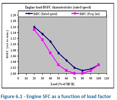
It is well known that the diesel engine's efficiency is a function of its load level or its load factor. Figure 6.1 shows the engine Specific Fuel Consumption (SFC) as a function of the load factor.

Load factor: The engine load factor is defined as the actual power output of the engine relative to its Maximum Continuous Rating (MCR). The Load factor is normally specified in percent. An engine working at 50% of its maximum load has a load factor equal to 50%.

/>
Engine load factor
Fig 6.1: Engine load factor

In Figure 5.1, the curve for constant engine speed operation (rated speed) represents the operation of electric generation engines (such as auxiliary engines, e.g., diesel generators), and the curve for propeller law shows the main engine operating characteristics. As can be seen, there is no significant difference, and for both types of applications, the engine's SFC varies with the engine load. SFC is a minimum (i.e., efficiency is a maximum) for a certain load level; typically for engines, it is in the range of 70 to 90% of an engine's Maximum Continuous Rating (MCR).

The above diagram also shows that under low load conditions, the SFC of the engine will increase (engine efficiency will reduce). Although the load on the main engine is primarily dictated by ship speed, the load on the auxiliary engines depends on the shipboard electrical loads that are a function of the number of machines, machinery and equipment being used at each point in time plus the number of engines used to satisfy the requirements.

In this web page, it is argued that engine loads should be managed, where possible, so that the engine fuel consumption is minimized. It will effectively mean operating the engines at 70 to 90% load range as discusses above regarding Figure 6.1.

Load management for main engine

For the main engines in a direct-drive or gear-drive configurations (mechanically linked to the propeller), there is not much that can be done as far as load management is concerned as normally ships have one main engine and load management normally applies to cases with more than one engine.

It should be noted that it is easy to show that the slow steaming leads to the main engine’s operation at low loads at a less efficient load factor . Overall, this low-efficiency operation of main engine has been accepted by industry since the impact of reductions in ship resistances on a ship’s fuel consumption is much more effective than increases in the main engine’s SFC for slow steaming cases.

increase in fuel vs hull roughness


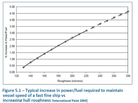
Fig 5.1: Typical increase in power/fuel required to maintain vessel speed of a fast fine ship vs increasing hull roughness [International Paint 2004]. Therefore in main engines, a non-optimal operation may be allowed due to slow steaming because of slow steaming greater benefits. However, in such conditions and if slow steaming is going to continue for the long term, engine performance characteristics are recommended via changes to turbochargers, injection systems, and other engine settings (engine adjustments for slow steaming optimized operation).

No matter what load the main engine is operating under, it is mostly recommended that the main engine load be kept at a reasonably steady level under regular operation. It is achieved by keeping the engine speed (RPM) constant. Frequent changes to the shaft rpm, thus engine load, are not efficient and must be avoided

Load management for auxiliary engines

There is ample evidence that load management for auxiliary engines is an effective way to reduce the engines' fuel consumption and maintenance costs. Each ship normally has three or more auxiliary engines, each connected to one electric generator. The engine and generator as a combined system are normally referred to as diesel-generator (DG).

Onboard ships, and often in order to assure against a blackout, two DGs are operated for long periods at less than 50% load factor. The periods for which these conditions are sustained can include all discharge ports, standby periods, tank cleaning periods, movement in restricted waters and ballast exchange periods.

This often leads to unnecessary simultaneous usage of multiple engines; at low load factors and beyond requirements. As a result, low load factor leads to poor energy efficiency performance. Additionally, the operation of diesel engines at low loads causes poor piston ring seal, sub-optimum turbocharger performance, low specific fuel consumption, elevated thermal stresses and increased specific lube oil consumption. In short, it leads to more maintenance and higher fuel consumption.

periods for running 1-DG and 2-DG for a tanker
Figure 6.2 shows the periods for running 1-DG and 2-DG for a tanker

Method of analysis

To evaluate the prevailing practices on the use of auxiliary engines, the following areas need to be investigated:
  1. The load factor of various ship's DGs needs to be established via collection and analysis of data. This measurement is quite straightforward as the DGs' power output is normally measured and presented in the Engine Control Room.
  2. Alternatively, the engines utilisation factors11 can be estimated. It can easily be estimated from the records of engine run hours that are available every month. From utilization factors for all the engines, it can then be established the periods that one DG (1-DG), two DGs (2-DGs), or more DGs have been simultaneously operated.
  3. The next step is to evaluate if the utilisation of engines are excessive. It will require the evaluation of ship operation profile versus the number of DGs required for operational or safety purposes. Benchmarks will need to be developed for this purpose.
  4. Final phase is to identify methods by which the run hours of the engines could be reduced; thus save fuel.


As an example of such analysis, Figure 6.2 shows the periods for running 1-DG and 2-DG for a tanker. For this specific tanker, an analysis of the operational profile indicated a period for 2-DG operation is excessive, and it may be reduced from 48% of the total time to a lower number. It will result in improved energy efficiency and maintenance (see case study for estimating the benefits at the end of this section).

Method of improvements

There are two ways of improving engine load factors and reducing engine utilization factors:

Avoid use of multi-engine parallel operation when not needed. To achieve this, careful planning of shipboard activities that require electric power and its implementation is a need. Also, there is a need to keep several operating engines to a minimum as per requirements and avoid the deliberate operation of multi engines when not need.

the demand side must also be managed via better system planning for load reduction. The reduction of loads in this way helps to provide better load management on DGs and avoids the running of two engines at low loads. As part of this, proper management of a ship's electrical demand, including load reduction and load scheduling, could be used to reduce the number of DGs in use and optimize the DGs' performance via a better load level.

Electrical load reduction

It is often possible to reduce energy consumption by working towards a more conscious and optimal operation of ship machinery and systems. These could be achieved more effectively if planned for each mode of operation. Examples of measures that can be considered include:

Avoidance of unnecessary energy use via switching off the machinery when not needed. All non-essential and not-required machinery and equipment that do not affect the ship and personnel safety should be stopped while in port and at sea to reduce the load on diesel generators. Such items should be identified first and then procedures for the execution of tasks to be developed and implemented.

Avoidance of parallel operation of electrical generators; when one is sufficient for the purpose. This aspect is covered and fully discussed under "engine load management."

Optimized HVAC (Heating, Ventilation and Air Conditioning) operation on board. The HVAC system operation should be aligned to outside weather conditions either via automatic settings or manual operations (more important for cruise ships).

Proper coordination should be maintained on board between deck and engine departments especially for the use of machinery/equipment items such as steering gear motors, bilge and fire pumps, winches and mooring equipment, deck cranes and service and deck compressed air usage, etc., These help to reduce loads on generators. The above activities will lead to reduced electrical power demand. Moreover, jobs could be coordinated and bundled together so that two generators could be run more effectively and for a shorter period. This could be achieved via system planning and more coordinated actions.

Auxiliary machinery use reduction via system planning

There is a significant number of redundant machinery onboard ships; this allows ship operation when one fails as well as for safety-critical situations where two machinery needs to operate simultaneously. In practice, redundant machinery is normally used more than necessary. It could include any type of machinery in particular fans and pumps. Any reduction in the use of such machinery can lead to energy efficiency.

Proper planning of the use of several types of machinery versus operation mode effectively achieves this objective. The use of simultaneous use of multi machinery in parallel could be reduced via advanced planning and decision making on the number of machines to be used, taking into account the actual operational requirements.

For example, when the ship is in port, the plan should include switching off one or two engine room ventilation fans as the main engine is not operating anymore. Another example is the mooring equipment. When mooring equipment is not needed, the related pumps and machinery could be switched off.

To ensure safe operation, all these need to be proactively planned and executed. Without daily planning and the establishment of relevant processes, the task of reducing energy use cannot be accomplished. As emphasized before, coordination between deck and engine departments is of paramount importance for an effective and, at the same time, safe action to avoid misunderstanding or unexpected consequences.

Auxiliary fluid machinery

It refers to pumps, fans, compressors, etc. that are extensively used onboard ships. There are several opportunities to save energy with these machines that are briefly discussed. The main areas of evaluation include:

Sizing: The sizing of machinery against the actual operation requirements needs to be checked to identify cases of oversizing. It can be carried out by monitoring the machinery's operational performance against the manufacturer's specifications. Besides, the following may be indicative of oversized machinery:

For each machinery, a “capacity factor” can be defined that is indicative of over-sizing or under-sizing. Capacity factor may be defined as the “operational capacity” divided by “design nominal capacity”. A capacity factor significantly below or above unity is indicative of poor sizing or system’s operational anomalies.

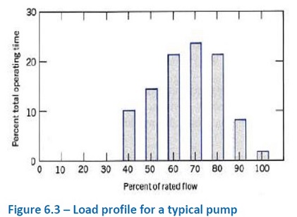
Load profile typical pump
Figure 6.3 – Load profile for a typical pump

Operation profile: The operation profile of machinery represents the machinery's load versus time. Continuously operated machinery at a certain load will represent a steady operation profile.

Machinery with highly variable load will represent a non-steady load profile. Load and operation profiles are normally presented in histogram format, an example of which is shown in Figure 6.3.

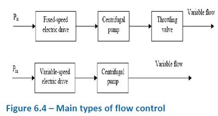
flow-control
Figure 6.4 main types of flow control

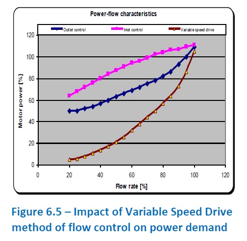
flow control for fluid rotating machinery
Figure 6.5 – flow control for fluid rotating machinery

From the operation profile, the operation management strategy of the machinery could be decided. In particular, the method of control and choice of on-off or Variable Speed Drive (VSD) modes can be established. For the variation of flow, two methods of flow control could be used (see Figure 6.4): The load profile for a multi-machinery setup could provide valuable information on method of load sharing strategy and management between machinery.

Operational aspects

Based on the above evaluation and basic characteristics of fluid machinery, the main opportunities for energy saving are:

Fouling reduction: Fouling in fluid machinery is a common cause of performance deterioration. Fouling can be controlled via best-practice maintenance activities. For examples, fans are susceptible to inlet fouling.

Mulit-machinery management: In general in a multi-machinery configuration (e.g., chiller plant compressors), the minimum number of machinery running for a particular duty represents the best machinery management strategy and ensures minimum overall machinery energy consumption.

Reducing idling mode of operation: In addition to operation of the machinery at optimal efficiency, it is prudent to reduce the none-productive operating hours of all machinery especially during port stays and also change over from on to off modes and vice a versa. In general the following policies should be implemented:

Electric Motors

Electric motors provide the drive system for the majority of ship auxiliary and hotel systems. In electric propulsion, electric motors are used for driving the propellers. Several ship auxiliary systems support the operation of the main power plant or required hotel services. Some of these are:
  1. Engine cooling system.
  2. Engine fuel system.
  3. Engines lube oil system.
  4. Compressed air system.
  5. Chiller plant for hotel HVAC system.
  6. Chiller plant for provision area.
  7. Steam system for hotel services and freshwater generation.
  8. Fresh water generation systems.
The main components of all the above systems are several rotating machinery, all driven by electric motors. Electric motors, excluding propulsion motors, consume the majority of the ship auxiliary electrical loads. Their efficient operation, therefore, is an important element of the overall ship energy management.

Basic characteristic

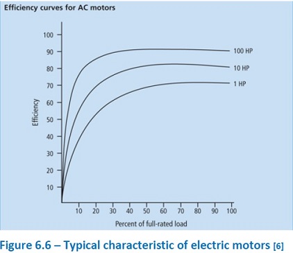
Electric motors used in ships are invariably of AC (alternative current) type. The typical characteristics of the electric motors are shown in Figure 6.6.

Typical characteristic of electric motors
Figure 6.6 – Typical characteristic of electric motors

According to Figure 6.6 and other relevant information on electric motors, the followings are applicable:

Electric motor efficiency is highest at its rated power. However, efficiency does not reduce significantly up to about 40%. Below 40% of rated power, efficiency reduces significantly. This threshold of 40% is lower for larger motors.

Electric motor efficiencies are usually below 80-90% depending on its size, denoting that there are losses associated with such motors. The loss is dissipated in the form of heat.

Main energy efficiency aspects associated with electric motors are as follows:

Sizing: The sizing of electric motors against actual performance needs to be checked to identify cases of oversizing. It can be identified via monitoring the performance data against the manufacturer's specification.

Operation profile: The operation profile of machinery is indicative of its load versus time. Continuously operated machinery at a nominal load will represent a steady operation profile. Machinery with the highly variable load will demonstrate a non-steady load profile.

Power factor: In electric motors, the power factor is defined as the ratio of the actual power in kW divided by power directly derived using current and voltage of machinery in kVAR. A low power factor means added electric network losses.

In dealing with shipboard electric motors, the above needs to be analyzed to find out about their relative efficiency and if there is a need to change any motors during technical upgrades to improve efficiencies. Technical upgrades should be generally considered within the ships' machinery maintenance programs.


References and further reading

The following list provides references for this section and additional publications that may be used for more in-depth study of topics covered in this section:

1. "IMO train the trainer course material," developed by WMU, 2013

2. OCIMF "Example of a Ship Energy Efficiency Management Plan," Submission to IMO, MEPC 62/INF.10, 8 April 2011.

3. ABS 2013 "Ship Energy Efficiency Measures, Status and Guidance, "http://ww2.eagle.org/ 4. MARSIG SEEMP Example, “Ship Energy Efficiency Plan, MARSIG mbH, Revision 0, 2012, http://www.marsig.com/

5. Bazari Z, 2012, "Ship Energy Efficiency – Developments and Lessons Learnt", Lloyd's Register, LRTA publication, November 2012.

6. "How to determine the efficiency of an electric motor using proxy brakes", http://electricalengineering-access.blogspot.co.uk/2015/03/how-to-determine-efficiency-of-electric.html,


Read more on

Energy efficiency measures -Trim optimization

Energy efficiency measures- Ballast water management

Energy efficiency measures- Causes of Hull roughness and preventive measures

Energy efficiency measures- hull roughness reduction

Energy efficiency measures- propeller maintenance

Energy efficiency measures- engine load management

Energy efficiency measures- fuel management

Energy efficiency measures - ship maintenance requirement

Read more on

Pollution by oil [Marpol Annex I ]

What is toxic releases onboard and associated hazards? ....

How to report in case of an oil spillage onboard

Oil disaster prevention

Handling guideline for oil cargo

Oil pollution prevention method


Related articles

Oil spillage prevention procedure

Pollution by other harmful substances & harmful packaged goods

Pollution by garbage [ Marpol annex V ]

Pollution by sewage [ Marpol annex IV ]

Pollution of air [ Marpol annex VI ]

Prohibition on use of harmful (TBT) anti-fouling paints

Pollution by ballast water

Prevention of pollution while carryiung out overboard maintenance

Environment friendly purchasing

Decommissioning / ship recycling

Environmental awareness


Other info pages !

Ships Charterparties Related terms & guideline
Stevedores injury How to prevent injury onboard
Environmental issues How to prevent marine pollution
Cargo & Ballast Handling Safety Guideline
Reefer cargo handling Troubleshoot and countermeasures
DG cargo handling Procedures & Guidelines
Safety in engine room Standard procedures
Questions from user and feedback Read our knowledgebase
Home page


ShipsBusiness.com is merely an informational site about various aspects of ships operation,maintenance procedure, prevention of pollution and many safety guideline. The procedures explained here are only indicative, not exhaustive in nature and one must always be guided by practices of good seamanship.

User feedback is important to update our database. For any comment or suggestions please Contact us
Site Use and Privacy - Read our privacy policy and site use information.
//Home //Terms and conditions of use

Copyright © 2015 www.shipsbusiness.com All rights reserved.